
Page 15 - TransAT_Tutorial_Manual
P. 15
TransAT Tutorial Manual 1.1. Turbulent Channel Flow
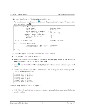
Now conditions for each of the boundaries should be set.
• For each boundary condition, press to open the parameters window, set the parameters
listed below then click .
Inflow −> Basic Properties :
Inflow Type : Velocity based
Inflow P r o f i l e : Turbulent
Inflow Velocity component (u ) : 3.0
Inflow S t a t i c Temperature : 300 ( Default )
Turbulence (RANS) Properties :
Turbulence i n t e n s i t y : 0.1
Mu t/Mu: 20
Outflow −> Outflow Type : Velocity ( Default )
Wall −> Basic Properties :
Temperature/Heat f l u x choice : Temperature
Temperature/Heat f l u x value : 320 K
Symmetry
To assign the Inflow boundary condition to the XMIN 0 surface
• Click the face XMIN 0 in the surface tree
• Select the Inflow boundary condition by ticking the light grey square to the left in the
appropriate line of the boundary conditions table
• Press . The XMIN 0 face will now be highlighted in both the surface list and the graphical
viewer.
• Proceed similarly using the data in the following table to assign the other boundary condi-
tions to their respective faces.
Boundary XMIN 0: Inflow
Boundary XMAX 0: Outflow
Boundary YMIN 0: Wall
Boundary YMAX 0: Wall
Boundary ZMIN 0: Symmetry
Boundary ZMAX 0: Symmetry
The final setup should be similar to Figure 1.1
• Click Files then select Save to save the settings. Alternatively, you can press Ctrl+s to
save the settings.
c
Ascomp AG Switzerland 5 Version 5.7