
Page 358 - TransAT_Tutorial_Manual
P. 358
TransAT Tutorial Manual 9.1. Water suction
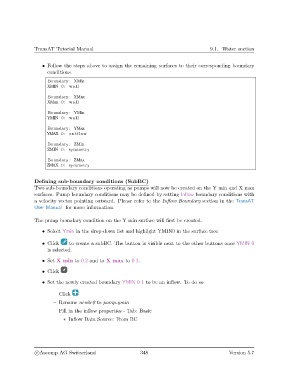
• Follow the steps above to assign the remaining surfaces to their corresponding boundary
conditions.
Boundary : XMin
XMIN 0: wall
Boundary : XMax
XMax 0: wall
Boundary : YMin
YMIN 0: wall
Boundary : YMax
YMAX 0: outflow
Boundary : ZMin
ZMIN 0: symmetry
Boundary : ZMax
ZMAX 0: symmetry
Defining sub-boundary conditions (SubBC)
Two sub-boundary conditions operating as pumps will now be created on the Y min and X max
surfaces. Pump boundary conditions may be defined by setting Inflow boundary conditions with
a velocity vector pointing outward. Please refer to the Inflow Boundary section in the TransAT
User Manual for more information.
The pump boundary condition on the Y min surface will first be created.
• Select Ymin in the drop-down list and highlight YMIN0 in the surface tree
• Click to create a subBC. The button is visible next to the other buttons once YMIN 0
is selected.
• Set X min to 0.2 and to X max to 0.3.
• Click
• Set the newly created boundary YMIN 0 1 to be an inflow. To do so
– Click
– Rename newbc0 to pump ymin
– Fill in the inflow properties - Tab: Basic
∗ Inflow Data Source: From BC
c
Ascomp AG Switzerland 348 Version 5.7