
Page 376 - TransAT_Tutorial_Manual
P. 376
TransAT Tutorial Manual 9.2. Forced Convection in an Isothermal Pipe
• Click
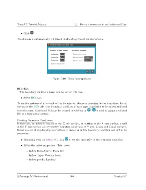
The domain is automatically cut into 3 blocks of equivalent number of cells.
Figure 9.10: Block decomposition
BCs Tab
The boundary conditions must now be set for this case.
• Select BCs tab.
To see the surfaces of all or each of the boundaries, choose a boundary in the drop-down list at
the top of the BCs tab. One boundary condition of each type is available to be edited and used
from the start. Additional BCs can be created by clicking on . is used to assign a selected
BC to a highlighted surface.
Creating Boundary Conditions:
In this case, an inflow is located at the X min surface, an outflow at the X max surface, a wall
at the Y max surface and symmetry boundary conditions at Y min, Z min and Z max surfaces.
Below is a set of step-by-step instructions to create an inflow boundary condition and define its
properties.
• Beginning with the Inflow BC, click to set the properties of the boundary condition
• Fill in the inflow properties - Tab: Basic
– Inflow Data Source: From BC
– Inflow Type: Velocity based
– Inflow profile: Laminar
c
Ascomp AG Switzerland 366 Version 5.7