
Page 264 - TransAT_Tutorial_Manual
P. 264
TransAT Tutorial Manual 6.2. countercurrent
Domain & Grid
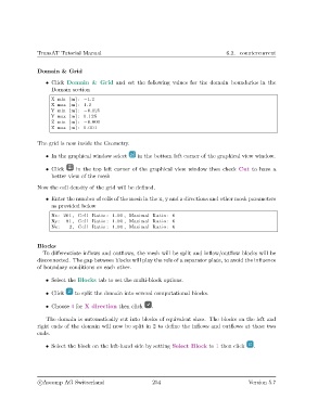
• Click Domain & Grid and set the following values for the domain boundaries in the
Domain section
X min [m] : −1.2
X max [m] : 1.2
Y min [m] : −0.125
Y max [m] : 0.125
Z min [m] : −0.001
Z max [m] : 0.001
The grid is now inside the Geometry.
• In the graphical window select in the bottom left corner of the graphical view window.
• Click in the top left corner of the graphical view window then check Cut to have a
better view of the mesh
Now the cell density of the grid will be defined.
• Enter the number of cells of the mesh in the x, y and z directions and other mesh parameters
as provided below
Nx: 201 , Cell Ratio : 1.00 , Maximal Ratio : 6
Ny: 81 , Cell Ratio : 1.00 , Maximal Ratio : 6
Nz : 2 , Cell Ratio : 1.00 , Maximal Ratio : 6
Blocks
To differentiate inflows and outflows, the mesh will be split and inflow/outflow blocks will be
disconnected. The gap between blocks will play the role of a separator plate, to avoid the influence
of boundary conditions on each other.
• Select the Blocks tab to set the multi-block options.
• Click to split the domain into several computational blocks.
• Choose 4 for X direction then click .
The domain is automatically cut into blocks of equivalent sizes. The blocks on the left and
right ends of the domain will now be split in 2 to define the inflows and outflows at these two
ends.
• Select the block on the left-hand side by setting Select Block to 1 then click .
c
Ascomp AG Switzerland 254 Version 5.7