
Page 302 - TransAT_Tutorial_Manual
P. 302
TransAT Tutorial Manual 7.2. coupling slug
– TransAT filename: T2O.txt
– 1D-code Boundary tag: P-tag
– 1D-code Oil Source tag: O-tag
– 1D-code Gas Source tag: G-tag
– 1D-code Water Source tag: W-tag
• Select Geometry on the left-hand side of the coupling configuration window.
• Set the pipe diameter to 0.08m.
• Select Coupling Scheme on the left-hand side of the coupling configuration window.
• Set the coupling boundary control parameters as follows:
– Pressure equation tolerance: 0.01
– Outflow velocity tolerance: 0.01
– Mass flux tolerance: 0.01
Assigning Boundary Conditions: To assign the water inflow boundary condition the Z min surface
• Select Z Min from the drop-down list at the top of the BCs tab
• Highlight ZMin0 in the surface tree
• Check the light grey square at the line corresponding to the water inflow boundary condition
• Click
ZMin 0 in the surface tree is colored with the color associated to the water inflow boundary
condition after being assigned.
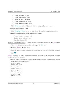
• Proceed as above to assign the corresponding boundary conditions to the remaining surfaces
using the information given below
Boundary : ZMax
ZMax 0: a i r i n f l o w
Boundary : XMin
XMin 0: symmetry
Boundary : XMax
XMax 0: coupling
Boundary : YMin
YMin 0: symmetry
c
Ascomp AG Switzerland 292 Version 5.7