
Page 313 - TransAT_Tutorial_Manual
P. 313
TransAT Tutorial Manual 7.2. coupling slug
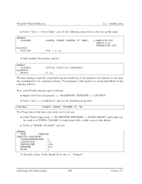
• Select “Add >> ServerData” and set the following properties on the tab on the right
GENERAL
VARIABLE : GASMFR, OILMFR, WATMFR, PT, TM[K] # MAKE SURE YOU
SELECT K AS
TEMPERATURE UNIT
POSITION
POSITION : POS−1, P−tag
• Add another Serverdata, and set:
GENERAL
VARIABLE : DPDGGS, DPDGLTHLS, DPDGLTWTS
EQUIPMENT
SOURCE : G−tag
The last setting is used for communicating the sensitivity of the pressure with respect to the mass
flux exchanged at the coupling interface. The purpose of this input is to avoid instabilities of the
coupling scheme.
Now, some Profile outputs can be defined.
• Right-click Flow Component >> FLOWPATH: PIPELINE >> OUTPUT
• Select “Add >> ProfileData” and set the following properties:
VARIABLE : GASMFR, OILMFR, TWATMFR, PT, TM
The Properties of the two nodes now need to be set.
• Click ”Flow Component >> FLOWPATH: PIPELINE >> NODE: INLET”, and make sure
the node is of TYPE: CLOSED. It looks black with a white cross in the sketch.
• Click on ”NODE: OUTLET” and set:
GENERAL
TYPE : PRESSURE
PRESSURE CONDITIONS:
TOTALWATERFRACTION : 1
GASFRACTION : 0.5
TEMPERATURE : 300K
PRESSURE : 1bar
FLUID : 1
In the last section of the Model View tab, i.e. “Output”
c
Ascomp AG Switzerland 303 Version 5.7