
Page 427 - TransAT_Tutorial_Manual
P. 427
TransAT Tutorial Manual 10.3. Droplet Impact on a Flat Plate
In this case, a wall is located on X max surface and symmetry conditions are applied on the re-
maining surfaces. Below step-by-step instructions are given to create the wall boundary condition
and define its properties.
• From the Wall BC available, click to set the properties of the boundary condition
• Select the Interface Tracking tab
• Set Contact Angle to 118 ◦
• Click to save the settings and close the window
Assigning Boundary Conditions:
• Select boundary X Min from the drop-down list at the top of the BCs tab
• By a simple click, highlight XMIN 0 in the surface tree
• Tick (light grey square) symmetry in the boundary conditions table
• Click
XMin 0 in the surface tree takes the color of the boundary condition after being assigned.
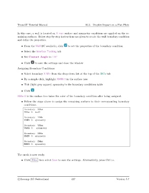
• Follow the steps above to assign the remaining surfaces to their corresponding boundary
conditions.
Boundary : XMax
XMax 0: wall
Boundary : YMin
YMIN 0: symmetry
Boundary : YMax
YMAX 0: symmetry
Boundary : ZMin
ZMIN 0: symmetry
Boundary : ZMax
ZMAX 0: symmetry
The mesh is now ready.
• Click Files then select Save to save the settings. Alternatively, press Ctrl+s.
c
Ascomp AG Switzerland 417 Version 5.7